- Today
- Total
| 일 | 월 | 화 | 수 | 목 | 금 | 토 |
|---|---|---|---|---|---|---|
| 1 | ||||||
| 2 | 3 | 4 | 5 | 6 | 7 | 8 |
| 9 | 10 | 11 | 12 | 13 | 14 | 15 |
| 16 | 17 | 18 | 19 | 20 | 21 | 22 |
| 23 | 24 | 25 | 26 | 27 | 28 |
- 재능이의 돈버는 일기
- StresslessLife
- K_JIN2SM
- 소소한 일상
- My Life Style & Memory a Box
- Blog's generation
- 공감 스토리
- 취객의 프로그래밍 연구실
- Love Me
- Dream Archive
- 세상에 발자취를 남기다 by kongmingu
- hanglesoul
- 카마의 IT 초행길
- 느리게.
- 미친듯이 즐겨보자..
- Joo studio
- Gonna be insane
- 악 다 날아갔어!! 갇대밋! 왓더...
- xopowo05
- 맑은공기희망운동
- 엔지니어 독립운동
- 혁준 블로그
- Simple in Complex with Simple
- 무의식이 의식을 지배한다
드럼치는 프로그래머
[시스템분석및설계] 17, 18장 무선 통신 제어기 설계, 라인 트레이서 로봇 설계 예비레포트 본문
[시스템분석및설계] 17, 18장 무선 통신 제어기 설계, 라인 트레이서 로봇 설계 예비레포트
드럼치는한동이 2008. 3. 14. 02:48◎ 실험 목적
▶ 무선 통신 제어기와 라인 트레이서 로봇의 동작을 VHDL로 기술하고, 시뮬레이션을 통해 동작을 검증한다.
◎ 이론 설명
▶ 무선 통신 제어기 설계
① RF (Radio Frequency) 통신이라고 불리는 무선 통신은 데이터를 전달하는데, 전선 같은 것이 필요 없이 처리 가능한 시스템을 일컫는다.
② 무선이란 게 성립하려면, 전선이 아닌 공기 중에 신호를 보내고 받아야 하는데 바로 그 러한 역할을 하는 게 전파이다.
④ RF 회로 설계가 어려운 가장 큰 원인은, RF에서 다루는 주파수가 매 우 높은 고주파가 많기 때문인데, 주파수가 높으면 파장이 짧아지고, 그 때문에 선로 간 간섭도 심해지며 선로 길이 하나하나가 회로 소자 로 동작해 버리기 때문이다.
저주파에서는 회로가 설계된 대로 동작된다.
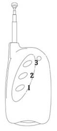
⑤ 본 키트에서 사용하는 무선 통신 주파수는 311MHz로, 데이터는 통신 방식 중의 하나인 AM(Amplitude Modulation) 변조를 하여 송신 하도록 되어 있다. < 3 Key 리모콘 송신기 >
⑥ 송수신을 원하는 송신기와 수신기 모듈의 어드레스 핀은 일치시켜 놓는다. 송신기에서 데이터를 송신할 때에는 이 어드레스 데이터도 동시에 송신한다. 따라서 비록 수신기에 의해 수신된 신호라 하더라도 정해진 어드레스가 아니면 데이터를 무시해 버리면 되는 것 이다.
▶ 라인 트레이서 로봇 설계
① 라인 트레이서(Line Tracer)란 바닥에 그려져 있는 선(line)을 따라가는 로봇을 일컫는다.
② 주행선은 흰바탕에 검은 선으로 만들거 나, 아니면 반대로 검정 바탕에 흰 선으 로 만들 수도 있다.
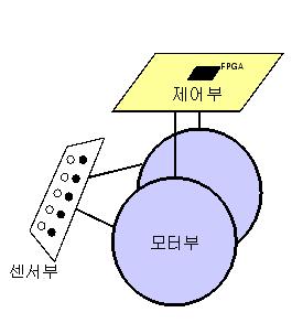
③ 로봇이 선을 따라 가게 하는 방법은 로봇 앞부분에 선을 감지할 수 있는 센서부와 이동 하기 위해 바퀴를 굴려 주는 모터부, 그리고 선을 잘 따라가도록 판단하고 제어해 주는 제어부를 가진 형태이다.
< 라인 트레이서 구성도 >
◎ 실험 장비
▶ Xilinx ISE
▶ ModelSIM
▶ Rov-Lab 트레이닝 키트
◎ 실험 순서
▶ 무선 통신 제어기 설계
① 무선 통신 제어기의 동작을 VHDL로 기술
library IEEE; use IEEE.STD_LOGIC_1164.ALL; use IEEE.STD_LOGIC_ARITH.ALL; use IEEE.STD_LOGIC_UNSIGNED.ALL; entity rf_con is Port ( RF_DATA : IN std_logic_vector (2 downto 0); LED : OUT std_logic_vector (2 downto 0); end rf_con; archicture Behavioral of rf_con is begin LED <= RF_DATA; end Behavirol;
< 무선 통신 제어기의 VHDL Test Bench 코드 >
*** Test Bench - User Defined Section *** tb : PROCESS BEGIN wait for 500 ns; --will wait forever END PROCESS; PROCESS BEGIN L1 : LOOP RF_DATA <= "000"; wait for 50 ns; RF_DATA <= "001"; wait for 50 ns; RF_DATA <= "010"; wait for 50 ns; RF_DATA <= "011"; wait for 50 ns; RF_DATA <= "100"; wait for 50 ns; RF_DATA <= "101"; wait for 50 ns; RF_DATA <= "110"; wait for 50 ns; RF_DATA <= "111"; wait for 50 ns; END LOOP L1; END PROCESS; *** End Test Bench - User Defined Section ***
② TestBenchWaveform으로 시뮬레이션
주어진 입력(RF_DATA)에 따라 출력(LED)이
진리표대로 정확하게 출력되는지를 검증
③ 트레이닝 키트로 동작 검증
주어진 입력(RF_DATA)에 따라 출력(LED)이
진리표대로 정확하게 출력되는지를 검증
▶ 라인 트레이서 로봇 설계
① 라인 트레이서 로봇의 동작을 VHDL로 기술
library IEEE; use IEEE.STD_LOGIC_1164.ALL; use IEEE.STD_LOGIC_ARITH.ALL; use IEEE.STD_LOGIC_UNSIGNED.ALL; entity line_tracer is Port(RSTB : in std_logic; CLK_4M : in std_logic; SENSE : in std_logic_vector(6 downto 0); LIGHT : out std_logic_vector(6 downto 0); MTL_A : out std_logic; MTL_B : out std_logic; MTL_nA : out std_logic; MTL_nB : out std_logic; MTR_A : out std_logic; MTR_B : out std_logic; MTR_nA : out std_logic; MTR_nB : out std_logic); end line_tracer; architecture Behavioral of line_tracer is signal clk_500 : std_logic; signal mtl_speed : std_logic_vector (1 downto 0); signal mtr_speed : std_logic_vector (1 downto 0); signal speed_l : integer range 0 to 25000; signal speed_r : integer range 0 to 25000; signal motor_lcnt : integer range 0 to 25000; signal phase_lclk : std_logic; signal motor_rcnt : integer range 0 to 25000; signal phase_rclk : std_logic; signal phase_lcnt : std_logic_vector (1 downto 0); signal phase_lout : std_logic_vector (3 downto 0); signal phase_rcnt : std_logic_vector (1 downto 0); signal phase_rout : std_logic_vector (3 downto 0); begin --=============Clock(500Hz)Generator ======================= process(RSTB, CLK_4M)
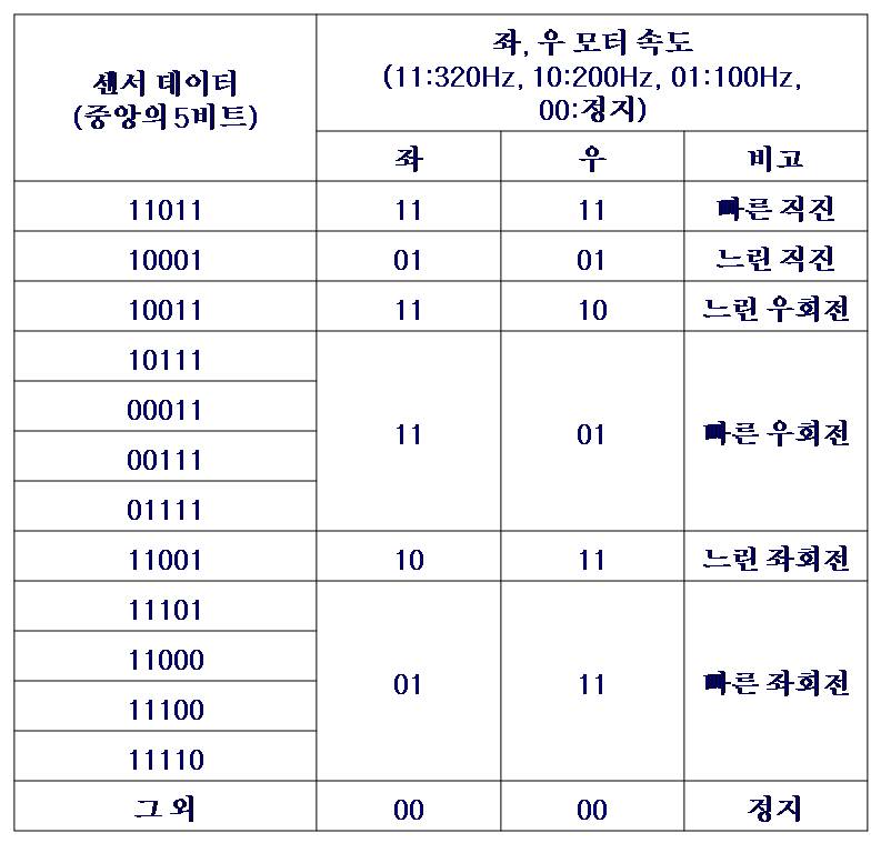
variable cnt : integer range 0 to 4000; begin if RSTB = '0' then cnt := 0; clk_500 <= '0'; elsif rising_edge (CLK_4M) then if cnt >= 3999 then -- 정상 동작시 -- if cnt >= 2 then -- 시물레이션시 cnt := 0; clk_500 <= not clk_500; else cnt := cnt + 1; end if; end if; end process; --============================================================================ Infrared Light Emission ========================= LIGHT(0) <= clk_500; LIGHT(1) <= clk_500; LIGHT(2) <= clk_500; LIGHT(3) <= clk_500; LIGHT(4) <= clk_500; LIGHT(5) <= clk_500; LIGHT(6) <= clk_500; --======== Line Status Sensing & 좌, 우 모터 속도값 결정 ============= process(RSTB, CLK_500) begin if RSTB = '0' then mtl_speed <="00"; mtr_speed <="00"; -- 느린 직진 endif falling_edge (CLK_500) then case SENSE is // 5개의 센서 비트로 판별 when "1110111" => mtl_speed <"11"; mtr_speed <="11"; -- 빠른 직진 when "1100011" => mtl_speed <"01"; mtr_speed <="01"; -- 느린 직진 when "1100111" => mtl_speed <"11"; mtr_speed <="10"; -- 느린 우회전
when "1000111" => mtl_speed <"11"; mtr_speed <="01"; -- 빠른 우회전 when "1001111" => mtl_speed <"11"; mtr_speed <="01"; -- 빠른 우회전 when "1011111" => mtl_speed <"11"; mtr_speed <="10"; -- 빠른 우회전 when "1110011" => mtl_speed <"10"; mtr_speed <="11"; -- 느린 좌회전 when "1111011" => mtl_speed <"01"; mtr_speed <="11"; -- 빠른 좌회전 when "1110001" => mtl_speed <"01"; mtr_speed <="11"; -- 빠른 좌회전 when "1111001" => mtl_speed <"01"; mtr_speed <="11"; -- 빠른 좌회전 when "1111101" => mtl_speed <"01"; mtr_speed <="11"; -- 빠른 좌회전 when others => mtl_speed <= "00"; mtr_speed <= "00"; -- 정지 end case; end if; end process; --======= 모터속도값에 따른 좌, 우모터 속도결정 ====================== process(mtl_speed) variable for_sim : std_logic; begin for_sim := -- 1 : 시물레이션시 0: 정상 동작시 if for_sim = '0' then case mtl_speed is when "00" => speed_l <= 0; -- 0 Hz when "01" => speed_l <= 19999; -- 100 Hz when "10" => speed_l <= 9999; -- 200 Hz when "11" => speed_l <= 6249; -- 320 Hz when others => speed_l <= 6249; end case;
when "10" => speed_l <= 4; when "11" => speed_l <= 2; when others => speed_l <= 2; end case; end if; end process; process(mtr_speed) variable for_sim : std_logic; begin for_sim := '0'; -- 1 : 시물레이션시 0: 정상 동작시 if for_sim = '0'; then case mtr_speed is when "00" => speed_r <= 0; -- 0 Hz when "01" => speed_r <= 19999; -- 100Hz when "10" => speed_r <= 9999; -- 200Hz when "11" => speed_r <= 6249; -- 320Hz when others => speed_r <= 6249; end case; else case mtr_speed is when "00" => speed_r <= 0; when "01" => speed_r <= 8; when "10" => speed_r <= 4; when "11" => speed_r <= 2; when others => speed_r <= 2; end case; end if; end process; -- 분주기 process(RSTB, speed_l, CLK_4M, motor_lcnt) begin else motor_lcnt <= motor_lcnt + 1; end if; end if; end process; -- 분주기 process(RSTB, speed_r, CLK_4M, motor_rcnt) begin if RSTB = '0' or speed_r = 0 then motor_rcnt <= 0; phase_rclk <= '0'; elsif rising_edge (CLK_4M) then if (motor_rcnt >= speed_r) then motor_rcnt <= 0; phase_rclk <= not phase_rclk; else motor_rcnt <= motor_rcnt + 1; end if; end if; end process; -=========== 왼쪽 모터 Phase Output(1상 여자방식) ================== process(RSTB, phase_lclk, phase_lcnt) begin if RSTB = '0' then phase_lcnt <= (others => '0'); elsif rising_edge (phase_lclk) then
when "11" => phase_lout <= "1000"; when others => phase_lout <= "0000"; end case; end if; end process; -=========== 오른쪽 Phase Output(1상 여자방식) ==================== process(RSTB, phase_rclk, phase_rcnt) begin if RSTB = '0' then phase_rcnt <= (others => '0'); elsif rising_edge (phase_rclk) then phase_rcnt <= phase_rcnt + 1; end if; end process; process(RSTB, phase_rcnt) begin if RSTB = '0' then phase_rout <= (others => '0'); else case phase_rcnt is when "00" => phase_rout <= "0001"; when "01" => phase_rout <= "0010"; when "10" => phase_rout <= "0100"; when "11" => phase_rout <= "1000"; when others => phase_rout <= "0000"; end case; end if; end process; --============================================================ MTL_A <= phase_lout(0); MTL_B <= phase_lout(1); MTL_nA <= phase_lout(2); MTL_nB <= phase_lout(3); MTR_A <= phase_rout(0); MTR_B <= phase_rout(1); MTR_nA <= phase_rout(2); MTR_nB <= phase_rout(3); end Behavioral;
< 라인 트레이서 VHDL 코드 작성 개념도 >
< 센서 데이터에 따른 좌,우 모터 속도 결정 >
② TestBenchWaveform으로 시뮬레이션
주어진 입력(RSTB, CLK_4M, SENSE)에 따라
출력 (LIGHT, MTL_A, MTL_B, MTL_nA, MTL_nB, MTR_A, MTR_B, MTR_nA, MTR_nB)이
진리표대로 정확하게 출력되는지를 검증
③ 트레이닝 키트로 동작 검증
주어진 입력(RSTB, CLK_4M, SENSE)에 따라
출력 (LIGHT, MTL_A, MTL_B, MTL_nA, MTL_nB, MTR_A, MTR_B, MTR_nA, MTR_nB)이
진리표대로 정확하게 출력되는지를 검증
'★─Multi Media > ☆─2학년 2학기' 카테고리의 다른 글
| [시스템분석및설계] 19장 원격 조정 로봇 설계 예비레포트 (2) | 2008.03.14 |
|---|---|
| [시스템분석및설계] 16,18장 적외선 센서 제어기 설계, 라인 트레이서 로봇 설계 결과보고서 (3) | 2008.03.14 |
| [시스템분석및설계] 16장 적외선 센서 제어기 설계 예비레포트 (0) | 2008.03.14 |
| [시스템분석및설계] 15장 스텝 모터 제어기 설계 결과보고서 (0) | 2008.03.14 |
| [시스템분석및설계] 14장 7 세그먼트 제어기 설계 결과보고서 (0) | 2008.03.11 |


